Da_Ephys
The DA_Epys panel centralizes control of data acquisition, including multiple hardware components necessary for performing electrophysiology experiments, such as the DAC, amplifier, and pressure regulators.
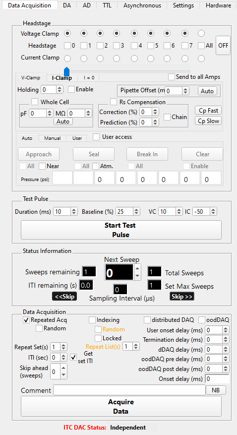
Main data acquisition panel
The main data acquisition panel centralizes and simplifies manual control of the amplifier, pressure control, test-pulse, and data acquisition for up to 8 headstages. For headstage dependent controls, the slider determines which headstage to apply user input.
Distributed DAQ (dDAQ)
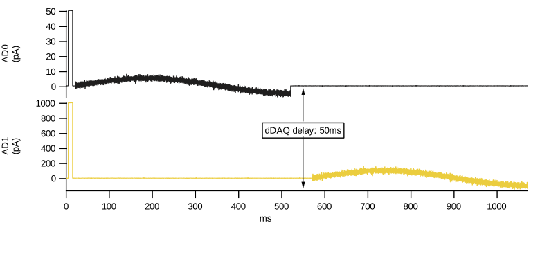
dDAQ simplifies the acquisition of synaptic responses during paired recordings. In paired recordings, each cell can be pre- and postsynaptic. dDAQ distributes the stimulus set sweep in time across headstages. Temporal distribution the stimulus set sweep ensures that the postsynaptic cell isn’t being stimulated simultaneously with the presynaptic cell, which would obscure any synaptic response(e.g., PSP, PSC). dDAQ delay inserts an acquisition time delay between the stimulus set sweeps on each headstage. dDAQ automatically adapts as headstages are enabled or disabled during data acquisition.
Optimized overlap distributed DAQ (oodDAQ)
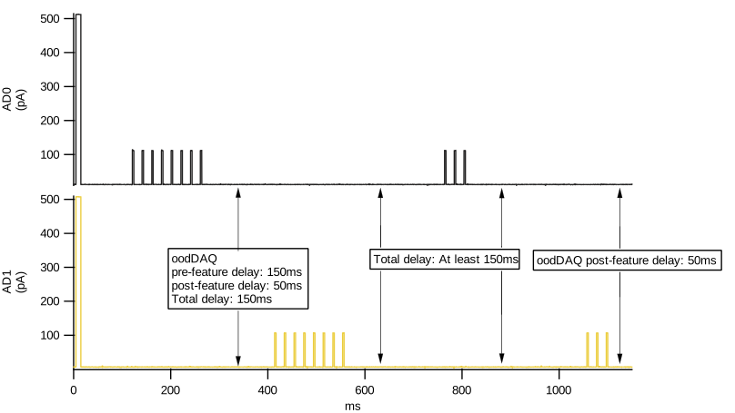
oodDAQ simplifies and speeds the acquisition of synaptic responses during paired recordings. In paired recordings, each cell can be pre- and postsynaptic. oodDAQ distributes the non-zero epochs of the stimulus set sweep in time across headstages. Temporal distribution of non-zero regions of the stimulus set sweep ensures that the postsynaptic cell isn’t being stimulated simultaneously with the presynaptic cell, which would obscure any synaptic response(e.g., PSP, PSC). oodDAQ pre- and post-delay extend the region of non-overlap to include zero regions around the non-zero region. These delays ensure the synaptic response can complete before the cell is stimulated to elicit a (presynaptic) action potential. Pre- and post-delay are highly recommended when the stimulus set sweep contains pulse trains. To maintain optimal stimulus distribution, oodDAQ automatically adapts if headstages are enabled or disabled during data acquisition.
TTL channels on NI DAC devices
MIES supports up to 8 TTL output channels on NI DAC devices. On NI hardware these TTL channels are delivered through Digital I/O (DIO) Port 0.
Physical connections
The mapping between MIES TTL channel numbers, NI DAQmx channel names, and the connector labels used on NI hardware is:
MIES TTL channel |
NI DAQmx channel name |
Physical connector label |
|---|---|---|
TTL0 |
|
|
TTL1 |
|
|
TTL2 |
|
|
TTL3 |
|
|
TTL4 |
|
|
TTL5 |
|
|
TTL6 |
|
|
TTL7 |
|
|
{DeviceName}is the NI-assigned device name shown in NI MAX, for exampleDev1.The exact physical pin number for each
P0.xlabel depends on the device model and the terminal block accessory in use. Consult the NI device pinout diagram and the documentation for the connected terminal block.MIES always uses Port 0 (
HARDWARE_NI_TTL_PORT = 0). This is fixed in the source code and cannot be changed from the GUI.
PFI pins
NI devices also provide PFI (Programmable Function Interface) pins such as
PFI0 and PFI1. These pins are digital lines, but they are not the TTL
data channels exposed by MIES on Port 0.
MIES utilizes PFI pins internally to manage timing and triggering tasks. Specifically, MIES uses PFI pins to synchronize data acquisition across multiple NI boards. For example, two NI PCIe-6343 boards can be combined to obtain 8 analog output channels by sharing start triggers and the sample clock over PFI lines.
The P0.x pins listed above are the MIES TTL output channels and are
controlled from the DA_Ephys TTL tab.
Pipette pressure control
The MIES TTL output channels on Port 0 serve as control lines for actuating solenoid valves that regulate pipette pressure, enabling switching of the pipette tip between user-applied pressure, the pressure regulator, and atmospheric pressure.
Enabling TTL channels in MIES
To enable TTL output channels in MIES:
Open the DA_Ephys panel.
Go to the TTL tab.
Check the TTL channel that you want to enable.
Select a stimulus set for that channel from the drop-down menu.
Hardware notes
MIES uses Port 0 exclusively on all supported NI devices.
The NI USB-6356 provides 8 DIO lines on Port 0 (
P0.0toP0.7), supporting all 8 MIES TTL channels.TTL channels are output-only during data acquisition. Do not drive these pins externally while MIES is running.
Each TTL channel is independent and can carry a different stimulus waveform.